HEPA Filter Leak Scanning
After assembly, a HEPA filter requires verification of filtration performance and local integrity under specified conditions. Overall efficiency describes the filter’s combined performance during a test, while leak scanning examines particle penetration at individual locations. Reading efficiency, resistance and location-based results together gives a more useful picture of the finished filter and supports subsequent quality decisions.
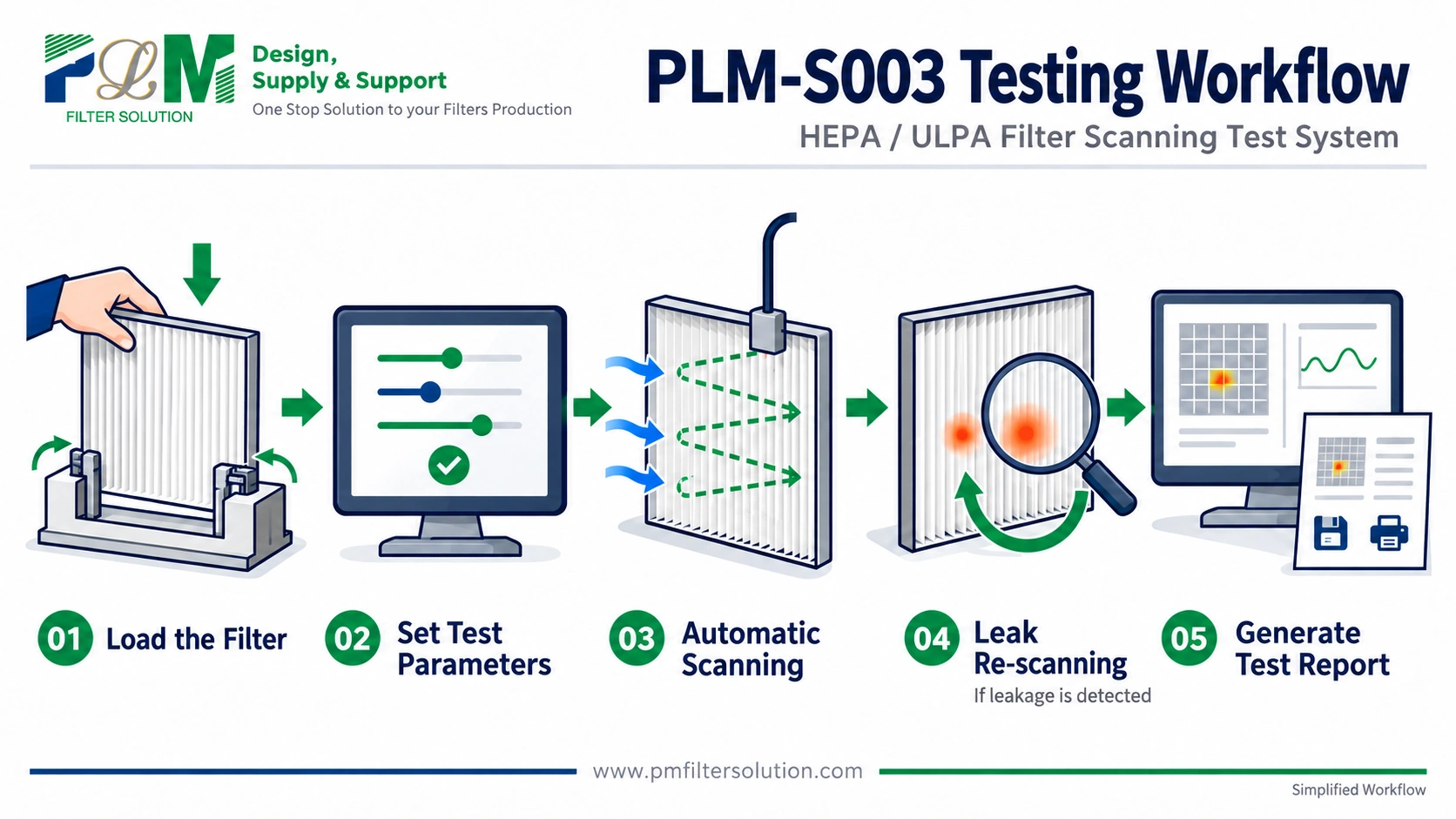
This article concerns particle-counting scan inspection of finished HEPA filters during manufacturing, rather than installed-system leak testing at the point of use. The PLM-S003 scanning test system serves as the equipment example. A complete inspection connects test preparation, mounting, point-by-point scanning, result interpretation, local re-scanning and report retention. The product’s specified test method and acceptance criteria determine how the measurements are evaluated.
Define the test task and operating conditions
Before testing, verify the product identity, dimensions, depth, construction and target classification, then define the required measurements. Rated airflow, frame geometry and sealing interfaces can differ between HEPA filters. Sharing a product label does not justify reusing every test setting. Check the product requirements against the available equipment range before the sample reaches the test station.
In particle-based testing, upstream aerosol supplies the challenge and downstream sampling measures particles passing through the filter. The relevant measurements support an efficiency result tied to those conditions. Scanning then associates downstream measurements with individual positions. Preparation establishes an interpretable relationship between airflow, particles and sample rather than merely placing a filter on the machine.
The PLM-S003 specification includes test airflow and resistance ranges, sampling flow, aerosol source and maximum sample dimensions. Compare these with the required test task to establish whether the proposed configuration is suitable. The available ranges describe equipment capability rather than product acceptance limits. Select the actual conditions and criteria through the applicable method and operating procedure, and confirm any specification-dependent configuration before routine testing.
For routine production, retain a checkable set of requirements for each product family and identify what must be reviewed during a changeover. Different dimensions can affect mounting and scan coverage; different constructions can affect access to the test face. Resolving these differences beforehand makes comparisons more meaningful and helps shifts use consistent conditions.
Translate the test task into a product-specific instruction that identifies the required efficiency measurement, local leakage inspection and resistance measurement at the specified airflow. State the result quantity, unit and acceptance criterion for each item. Where the method specifies a test particle size or counting channel, record that selection as well. Define scan settings through the applicable procedure, so that preparation produces a usable test instruction rather than a list of equipment ranges.
Control mounting and the test environment
The filter must be mounted through a suitable interface. Check seating, support, sealing contact surfaces and the prescribed clamping arrangement so that air follows the intended path through the sample. An unsuitable test interface can affect the result through an additional bypass. Interpret perimeter findings in the context of mounting, and document any adjustment before measuring again under the required conditions.
Check the mounting interface in a repeatable order: confirm sample orientation and support, examine sealing contact surfaces, then apply the prescribed clamping arrangement. Verify that the fixture does not conceal areas required for inspection. If a perimeter finding prompts remounting, record the specific adjustment and repeat the required measurement. Avoid changing several mounting conditions at once without a record, because the effect of each change then becomes difficult to explain.
The system provides automatic sample loading and unloading and a dedicated working clean area. These features support sample exchange and help limit external interference. Workshop practice should still control the sequence of loading and measurement and avoid unrelated movement during a run. A working clean area does not remove the need to check sample condition, local conditions and operator activity against the operating requirements.
Particle testing also requires a suitable aerosol challenge. Automatic concentration adjustment helps establish the required condition, but the target comes from the test method. Verify readiness according to the operating procedure. Review concentration, airflow and instrument status together rather than assuming that a programme being ready to start means the product can already be assessed.
After sample exchange, remounting or an interrupted run, determine which readiness checks must be repeated before measurement resumes. Record the interruption, any sample movement and the scan area already completed. The operating procedure should specify whether the run can continue or requires a new scan. Confirm that the final record demonstrates the required coverage and does not combine measurements from unexplained operating conditions.
Connect measured results to locations through scanning
Point-by-point scanning links local measurements to positions on the filter. It provides information about areas requiring attention beyond a single overall value. Follow the confirmed programme to cover the required media face and applicable connection or perimeter regions. The exact coverage depends on construction, the test interface and the selected method; a construction illustration alone cannot define the inspection scope.
Before starting the scan, confirm how the programmed path covers the required inspection area, including its start position and treatment of boundaries. Match the sampling arrangement and scan settings to the selected method and sample construction. If the sample moves or the run stops, preserve the completed record and assess whether coverage remains valid. Resume or restart according to the procedure, with the interruption and any repeated area identifiable in the inspection history.
Establish the sample orientation and a location reference before scanning so that report positions can be found on the physical filter. An identified corner, orientation or position numbering scheme can provide that link. Record any change when the sample is moved or turned. Keep location marks in the record or on a suitable reference carrier rather than introducing an unapproved operation on delicate media.
Sampling heads and templates can be customized for different testing requirements. Begin configuration discussions with the actual test face, sample dimensions, frame construction and coverage needs. Confirm how the proposed arrangement reaches the required media and applicable perimeter regions without obstruction. Establish the scan path, sampling arrangement and operating settings for the product before routine use; customization must result in a verified arrangement for the intended inspection task.
A location record matters only if it can be transferred back to the product. Turning a filter after testing can change what the next operator understands as the upper-left region. A reference edge or corner and recorded orientation give the scan, examination and re-scan a shared reference. Obstructions require access to be considered beforehand.
Read efficiency resistance and local findings together
Different results answer different questions. Overall efficiency describes combined performance, while minimum local efficiency and leak locations help identify spatial differences. A satisfactory overall result should not dismiss a local finding that fails the applicable criterion. Equally, one marked position does not establish every aspect of filter performance. Each result needs its definition, unit, test conditions and decision criterion.
For example, when an overall efficiency result meets its criterion but a local result does not, retain both and identify which requirement remains unsatisfied. Check the local result against its stated quantity and limit rather than comparing it directly with an overall efficiency percentage. Review the location and test conditions before investigation. The product remains subject to the applicable disposition procedure until every required acceptance item has been resolved.
Read resistance together with the airflow at which it was measured. Results obtained under different airflow conditions may not support a direct comparison. Check the actual conditions against the intended ones before interpreting efficiency, resistance and scan information. Keeping conditions with the values prevents records from different shifts or batches being compared as though they necessarily mean the same thing.
The system interface and report provide information on airflow, resistance, upstream concentration and downstream particle counts. Check the definitions of reported efficiency fields before using them: an average of scan-point values should not be assumed to be interchangeable with a separately measured overall efficiency. Review each field with its units, test conditions and applicable criterion. A local signal identifies an area for investigation; it does not by itself establish media damage, an adhesive gap or a mounting problem.
When comparing two records, first confirm that they concern the same product or a genuinely comparable product group. Then compare airflow, aerosol challenge, mounting and orientation, followed by the measurement quantities and units. Identify any changed condition before interpreting a difference in values or distributions. Graphs help reveal patterns, while the applicable acceptance rules determine the decision. Keep the comparison conditions visible in the record so another reviewer can reproduce the reasoning.
Use local re scanning to examine a suspect region
Local re-scanning allows further examination of an identified position. Before repeating the measurement, check sample identity, orientation, mounting and operating conditions. If the sample has moved or the setup has changed, document the change before deciding what comparison is meaningful. The value lies in an explained confirmation, rather than repeated testing until a passing value appears.
Prepare a local re-scan by retrieving the initial record and recovering its position reference on the sample. Confirm which region will be examined, the applicable criterion and whether mounting or operating conditions have changed. Keep the initial scan and the new result separately identifiable and link them to the same filter. This makes it possible to tell whether the re-scan confirms the original finding or evaluates the state after a documented adjustment or other action.
When the result changes, review remounting, handling and any other action between measurements. A change after correcting the mounting and a change after treating the product represent different events and should remain distinguishable. A persistently abnormal product requires disposition through the applicable quality procedure. Re-scanning capability does not itself authorize repair or release.
A local re-scan establishes the result for that region under those conditions. It does not automatically replace the finished filter’s required final inspection. After any intervention, the approved procedure determines subsequent coverage. Where complete scanning, overall efficiency, resistance or other specified measurements are required, complete and retain each applicable result. Record the inspection scope explicitly so local confirmation cannot be mistaken for completion of all acceptance obligations.
If the finding persists, retain the location and measurement evidence and refer the product for disposition through the applicable quality procedure. If it disappears, document any remounting, handling or operating change and explain what the new result supports. An unexplained change requires further assessment rather than deletion of the original finding. The final record should identify the required inspection scope, the results reviewed and the authorized disposition instead of preserving only the last passing value.
Retain reports as traceable quality records
The system generates a report after testing that can be printed or saved. Before routine use, confirm how the report identifies the sample, conditions, measured items and local findings, and determine what supplementary information must be linked through production records. Automatic report generation and complete product traceability are connected tasks; traceability also requires consistent identification and record management.
Before routine use, check that a reviewer can identify the filter, the measurement conditions and the results supporting its disposition. Determine which fields are present in the equipment report and which require a linked production record. Keep physical sample labels and electronic filenames consistent. If a run or report receives a new identifier during re-scanning, retain its relationship to the original inspection so the product history remains accessible.
Link the initial scan and subsequent re-scans to the same filter, retaining their sequence and any intervening action. Adding a new result should not erase the original finding. A reviewer should be able to follow how the issue was detected, how it was examined and which results supported the final decision. This supports current acceptance as well as later comparison and investigation.
When planning a PLM-S003 inspection station, provide the filter dimensions, depth, frame and seal construction, required airflow, inspection items and expected workload. Use these inputs to confirm sampling heads, templates and sample exchange arrangements. Review a representative report and the proposed mounting and scanning arrangement before routine production. This connects equipment selection with the actual product, the inspection method and the records needed by the production team.
Before accepting the record-management arrangement for routine use, ask another shift to retrieve a sample and its initial scan, a quality reviewer to identify the associated re-scans, and an engineer to locate any changed test conditions. Resolve missing links or ambiguous versions through a consistent naming and identification rule. For configuration discussions, prepare representative product drawings and test requirements alongside the expected workload so the proposed station can be assessed against a concrete production task.