Choosing the Activated Carbon Composite Process for Cabin Air Filters
A standard non-woven cabin filter captures dust and pollen, while a premium filter also needs to remove odors, exhaust gases, and VOCs from cabin air. The activated carbon composite process adds the carbon layer needed for this additional function and requires a different approach from ordinary media pleating. This article explains how the carbon layer is formed, why a dedicated composite machine is used, and which parameters affect carbon shedding and edge leakage.
For manufacturers planning a new line or upgrading an existing one, the key issue is how to laminate the activated carbon layer so that it remains evenly distributed, stays secure after pleating, and does not raise airflow resistance beyond the HVAC blower requirement. Equipment selection should therefore begin with the finished filter rather than a single machine model.
The Finished Structure Determines the Lamination Process
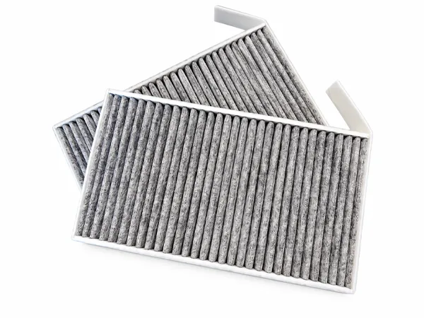
A pleated non-woven pack alone provides particle filtration. To also remove odors, VOCs, and exhaust gases, the media must be combined with a granular activated carbon layer before pleating. A typical premium cabin filter includes a pre-filter non-woven layer for coarse particles, an activated carbon layer for gas and odor adsorption, a support or protection layer to retain the carbon granules, and a fine non-woven layer for smaller particles.
This structure cannot be produced by simply scattering carbon onto a single web. The carbon must be secured between two media layers with controlled adhesive application to prevent shifting during pleating, carbon loss from cut edges, and uneven areas that can increase resistance and reduce adsorption capacity. A dedicated activated carbon composite machine is therefore used instead of an ordinary pleating line. The finished structure also defines the key performance requirements: the pre-filter and fine-filter layers affect particle efficiency, while carbon grammage and granule size influence adsorption capacity and airflow resistance. The media, carbon, adhesive, and edge system therefore need to be matched as one product set.
How the Activated Carbon Composite Machine Works
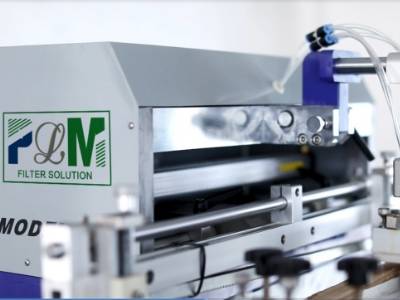
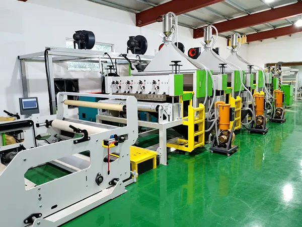
An activated carbon composite machine integrates unwinding, glue spraying, carbon dispensing and lamination, slitting, and rewinding in one continuous process. Two media webs and activated carbon granules are combined into a uniform composite roll ready for pleating and edge bonding.
The two media layers are fed in parallel under synchronized tension to maintain an even glue pattern. A controlled amount of hot-melt adhesive is applied to the carbon-carrying surface, activated carbon is dispensed at a controlled rate, and a lamination roller presses the second media layer onto the stack to secure the carbon between the two webs.
After lamination, the composite web is slit to the required width and rewound for pleating. Keeping the process synchronized helps maintain consistent carbon grammage and reduces uneven carbon distribution or adhesive blockage.
Key Parameters and Defect Control
Once the structure is defined, four parameter groups determine composite quality. The first is adhesive control, including adhesive type, glue add-on in grams per square meter, and spray uniformity. Too little glue can cause carbon shedding, while excessive or uneven glue can block media pores and increase resistance. The second is carbon load. Higher carbon grammage increases adsorption capacity but also raises airflow resistance, so it should be selected according to the target vehicle and filter grade rather than maximized. The third is granule size. Oversized granules may distribute unevenly and fall from pleat edges, while undersized granules can increase resistance and pass through the media. The fourth is lamination pressure and temperature, which must be sufficient to bond the layers without causing adhesive bleed-through or web deformation. Line speed must also remain matched to these parameters, as variation can lead to intermittent glue application and bare carbon areas.
These parameters are directly linked to common defects. Carbon shedding may result from insufficient glue, unsuitable adhesive, or weak lamination pressure. Uneven carbon or bare patches may indicate blocked spray nozzles, unstable web tension, or speed variation. Delamination or blistering can result from low glue temperature, insufficient pressure, or damp incoming media. High initial resistance and poor breathability are often associated with excessive carbon load or glue patterns that block the media surface. First-piece inspection helps identify these issues before full-batch production.
Quality verification should cover particle efficiency at the specified grade, initial airflow resistance at the rated air volume, carbon content and adsorption performance such as iodine or benzene adsorption value, and a shedding test that measures carbon loss after vibration or blowing. Appearance inspection should also check for uneven carbon distribution, glue streaks, and edge defects before edge bonding.
Match the Composite Process to the Filter
The composite stage should be evaluated as part of the complete cabin filter line rather than as a standalone machine. Because the activated carbon composite process feeds directly into pleating and edge bonding, composite roll width, pleat height, and the edge system should be matched as one product set. The edge system also helps prevent carbon from leaking through the cut sides.
The production route should reflect the product mix. A factory with a small number of stable models may use a continuous composite and pleating line with fixed tooling, while shorter runs and frequent model changes require greater attention to changeover, parameter recall, and first-piece confirmation. Existing pleating or bonding equipment can often be retained, with the composite stage added to address the actual bottleneck rather than replacing the entire line.
Start with Your Filter Requirements
For an initial review, provide:
- Front and back photos or a sample of the target filter.
- Required particle grade, odor/VOC target, and acceptable resistance.
- Media, carbon granule size, and adhesive information.
- Planned models, target output, available operators, workshop space, and utilities.
- Existing pleating or bonding equipment.
We have focused on filter production solutions since 1990, offering more than 70 types of filter production and test machines with ISO, CE, and CO certifications. A practical review starts with the target filter, matches the media, carbon, adhesive, and edge system as one product set, confirms sample results and first-piece criteria, and then defines layout, operators, utilities, installation, and training requirements. The right composite solution is one that matches the finished filter structure and can be repeated consistently in production.