Selecting and Processing Glass Fiber Media for HEPA Filters
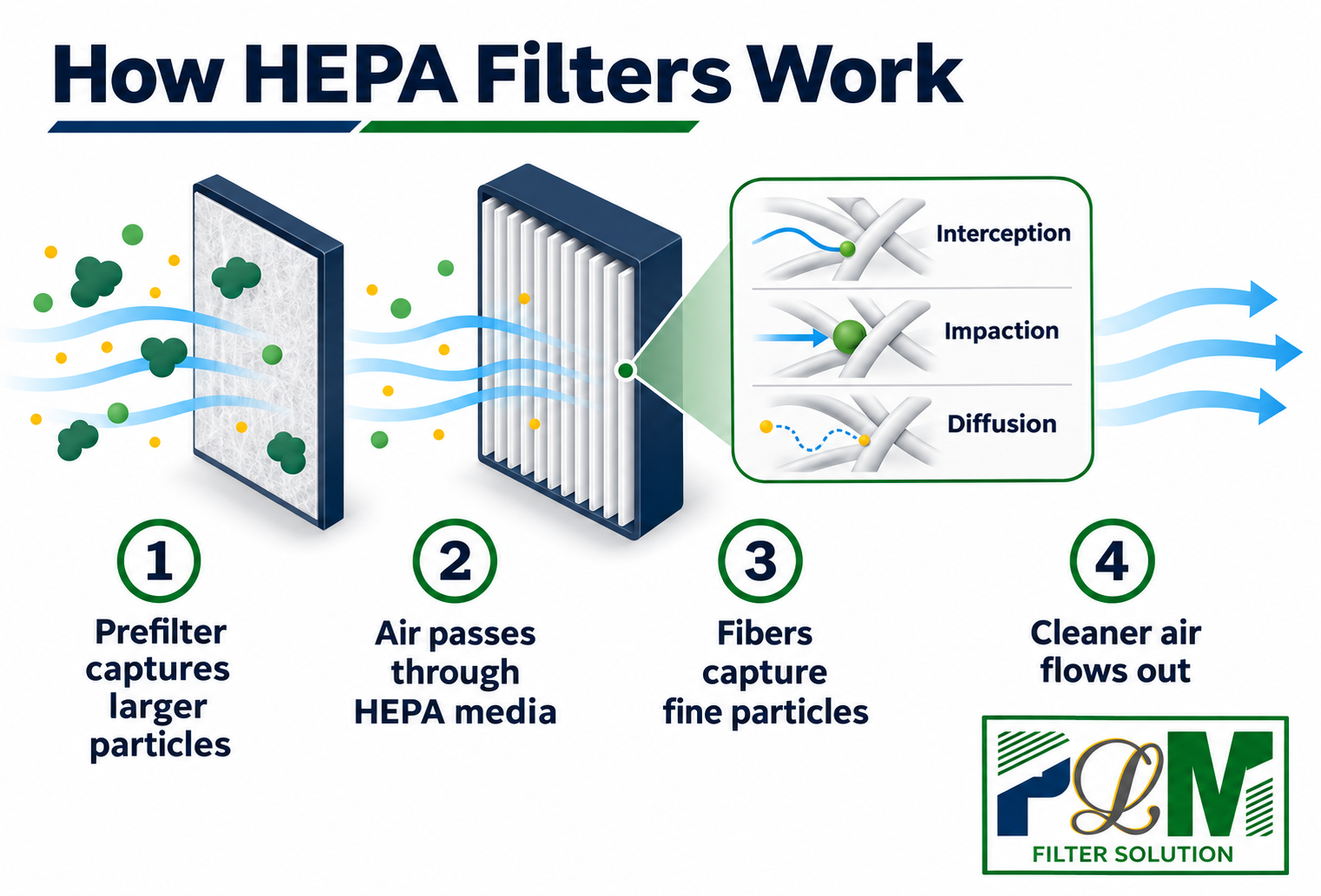
A HEPA filter must preserve the performance of its filtration medium through forming, assembly and use. Fine glass fiber media provide a filtration layer for high-efficiency air filters, while the pleat structure, frame and seal keep the airflow on its intended path. For manufacturers, selecting a suitable roll is the beginning of the task. The material must also be converted into a stable filter pack without damage or an unintended leakage path.
PLM Filter Solution supports this connection between media requirements and production equipment. By considering pleating, adhesive application, assembly and testing together, we help customers define a process around the finished filter rather than selecting each machine in isolation.
Select the media against the finished filter requirements
Glass fiber filter paper is a fibrous filtration sheet, distinct from a metal support mesh or a corrugated separator. The filtration layer captures particles, while the other components maintain or protect the pack structure. Identifying each layer’s role avoids treating a support material as evidence of filtration efficiency. It also makes the drawing and bill of materials more useful when discussing equipment.
Start with the required efficiency, rated airflow, allowable resistance, finished dimensions and service environment. Compare media data at the stated test conditions, then check thickness, roll width and the mechanical properties relevant to conversion. Record the test method, test aerosol or particle-size basis, media face velocity and pressure-drop conditions; compare grades only on a common basis. A material’s efficiency result and its resistance must be considered together; neither an appearance nor a single headline value fully describes suitability for a particular filter.
A media sample should therefore be evaluated alongside the intended pack depth, pleat height, pitch and sealing design. The grade that meets a material test still needs a practical forming window. Confirm the actual material specification before introducing heating, coatings or other treatments; processing conditions should follow the selected grade rather than a general glass fiber recipe.
Protect the sheet from unwinding through cutting
Glass fiber media can be sensitive to concentrated tension, sharp bending and repeated contact. During a trial, follow the sheet from the roll to the forming section and cutter. Check alignment, guide surfaces and contact pressure, and look for recurring damage at the same edge or fold. A local defect may be easier to trace to a contact point than to identify from a finished-filter test alone.
Use representative rolls and assess starts, stops and the intended operating speeds. Record pleat height, pitch, pack length and visible damage after cutting, then repeat the dimensional check after transfer. Compare the results with the drawing and approved sample, and record the media lot, machine speed and glue-line settings for repeat trials. This distinguishes a forming problem from deformation caused by handling. Keeping the pack supported during collection and transport helps preserve the geometry established at the machine.
Keep pleat spacing stable for the selected construction
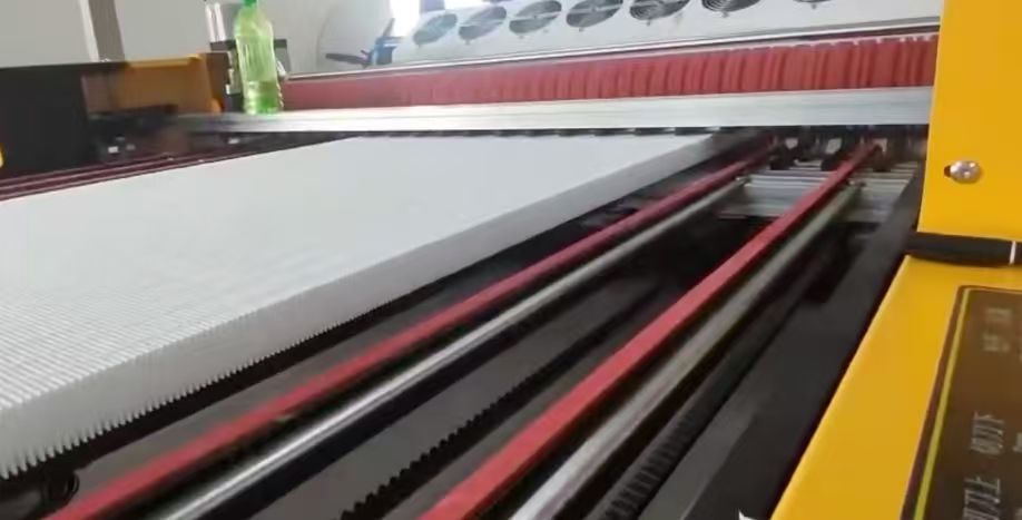
Pleating places a larger media area within a compact filter, but the spaces between the pleats must remain open. At a fixed pleat height and pack size, a tighter pitch can increase the amount of media while narrowing the airflow passages. Select the geometry against both the airflow requirement and manufacturing conditions. Check the pack in its assembled state, where compression or frame fit can change the spacing.
In a separatorless mini-pleat construction, hot-melt beads commonly maintain spacing. Adhesive compatibility, bead position, quantity and cooling before cutting all affect the result. During trials, check bead continuity, attachment to the selected media and whether the adhesive blocks airflow passages or distorts the pleats. Excess adhesive can occupy useful media area; insufficient or discontinuous support can allow the pleats to shift. Treat adhesive cooling and any later frame-sealant curing as separate process stages.
A separator construction uses inserted spacing material, typically corrugated paper or aluminium foil. Its profile, edge condition and insertion alignment must match the folded media. An uneven or misaligned spacer can distort the channels or damage the sheet. Both constructions require coordinated forming and assembly; the choice follows the product drawing and application requirements.
Our PLHP-1300A Glass Fiber Pleating Machine Without Partition provides automatic unwinding tension control, controlled glue application and cooling arrangements for the corresponding route. Its maximum processing width is 1250 mm, with a specified pleating-height range of 22–120 mm. These published limits help screen a configuration; they do not establish the usable width or operating settings for every media and pleat design. Material trials must confirm the working settings and pack geometry for the selected product.
Maintain the media to frame connection during assembly
The completed pack needs a continuous connection to the frame so that air follows the intended filtration path. Review pack squareness, frame fit and the designed sealing depth before applying sealant. A displaced edge or distorted corner can make the seal inconsistent even when the external dimensions appear correct. Inspect the interface after the required curing or setting period.
Protective screens and supports should also be selected around the structure and handling conditions. They can help protect delicate media, but they must not create damaging contact during assembly. Define how the filter is supported while it is moved, framed and packed. This carries the same attention to material integrity beyond the pleating station.
Verify the complete filter through performance and leakage tests
Finished-filter acceptance must address the specified efficiency, resistance and leakage requirements at defined conditions. Define the applicable standard or customer specification, rated test airflow, scan coverage and acceptance limits before testing. Media testing establishes information about the filtration sheet; testing the assembled filter also evaluates the effects of conversion and sealing. Where ISO 29463 is the agreed basis, flat-sheet media testing and completed-filter classification and testing address different test objects; a media result alone does not assign the finished filter a class. The agreed acceptance method and class should determine the test configuration, rather than assuming a universal efficiency claim for every glass fiber filter.
The PLM-S003 HEPA/ULPA Filter Scanning Test System supports point-by-point scanning, leak-location mapping and re-scanning of identified points. Its reporting functions help link an abnormal location to the filter surface or sealing interface for investigation. The published maximum sample size is 1220 × 1220 × 300 mm; for any actual filter, also confirm the fixture, orientation and accessible scan area, including applicable perimeter regions. Review the cause, complete any approved corrective work and retest under the specified conditions before release.
Keep results linked to the media lot, drawing revision, adhesive system and production settings. Repeated leakage along a fold can prompt a review of forming and handling; leakage near the perimeter calls for checks of framing and sealing. High resistance calls for a review of the material, pack geometry and assembly condition. These are investigation paths that need confirmation from process records and controlled trials.
Connect material selection with production support at PLM
PLM combines filter production equipment, testing equipment, filter materials and technical support within its service scope. For a glass fiber HEPA project, customers can review the media specification, spacing route, forming equipment and acceptance requirements together. This makes the role of each machine clearer and brings transfer, cooling and inspection needs into the configuration discussion.
Installation guidance, operator training, maintenance guidance and spare-parts support help carry the plan into daily operation. Share your media sample and technical data, finished-filter drawing, rated airflow, target output and acceptance requirements with our team. We can review a practical configuration around your product, current workshop and next production objective.