Oil Filter Production Line Stability Depends on Process Coordination
From paper inspection, pleating and curing to clipping and center-tube production, each stage of an oil filter production line must deliver stable, traceable semi-finished components for downstream assembly and testing. The line should operate as an integrated process, with each stage meeting the dimensional, structural and takt-time requirements of the next. Increasing the speed of a single machine does not necessarily result in stable mass production.
When an oil filter project begins, attention often focuses on the pleating machine model and production speed. These are important, but only part of the overall production plan. The spin-on fuel and oil filter process covers paper inspection, pleating, curing, cutting, clipping and center-tube production, followed by component preparation, assembly, seaming and leak testing. Stable production depends on aligning product dimensions, material standards and takt time across these stages.
Filter Paper Inspection Sets the First Quality Gate for Process Control
Filter paper should not enter the pleating process directly from storage without verification. Thickness, basis weight, air permeability, strength, impregnation and curing condition affect forming behavior as well as the pressure drop, dust-holding performance and structural stability of the finished element. If media conditions vary between lots while pleating and curing settings remain unchanged, paper cracking, pleat recovery, dimensional drift or unstable downstream bonding may occur.
Incoming inspection is therefore not only a pass/fail check; it also provides the basis for production settings. Filter-paper testing equipment may include PLKJ-20 and PLCP-1000. Inspection items should be defined according to the target filter, media specification and customer acceptance criteria, while lot identification should be retained for traceability to the material, machine settings or assembly stage.
Pleating, Curing and Cutting Must Maintain Dimensional Consistency
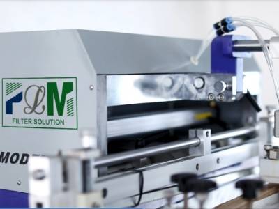
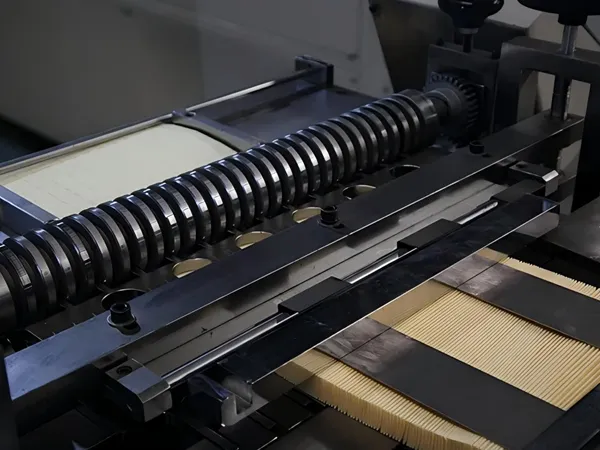
The pleater forms the folds, but a usable filter pack also depends on pre-slitting, marking, pleat height, pitch, count, heat forming and final cutting. Pleat height and count determine the filtration area and circumferential pack length, while paper width and cut length determine element height and assembly allowance. Recovery after curing determines whether the pack retains the shape required for the end caps and center tube.
If dimensions are checked only at the pleater outlet, changes after curing and cooling may not appear until assembly. An overlong pack may be compressed, resulting in crowded or leaning pleats, while an undersized pack may stretch at the joint or shift during positioning. Each SKU should therefore use validated process parameters for media width, pleat height, count, curing temperature, line speed and cut length. During changeovers, the approved parameter card should be restored instead of repeating the trial setup.
Clip Joint and Center Tube Control Ensures Structural Consistency
The two ends of the pleated pack require a reliable closure. Clip forming, clamping position and clip length affect both joint strength and circumferential dimensions. Insufficient clamping may allow the joint to open during assembly or service, while excessive or misaligned clamping can damage the paper, distort local pleat spacing and weaken end-cap bonding. PLJT-250 automates strip forming, clamping, cutting and resetting for fuel and oil filter elements.
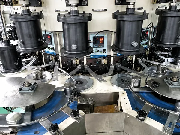
The center tube supports the element and forms the internal oil-flow path. Its diameter, length, material thickness, perforation pattern, spiral form and cut quality must match the pleated pack, end caps and target flow conditions. Variations in diameter or roundness affect assembly clearance, while length variation affects end-cap positioning. PLJY-75 is a fully automatic spiral center-tube machine for automotive oil and fuel filters, with adjustable tube diameter and cutting length. Final equipment selection should follow the actual product range, material and output requirements.
Downstream Assembly and Testing Reveal Upstream Variation
Once the pleated pack, joint and center tube enter assembly, upstream variation becomes an assembly issue. Inconsistent element height affects adhesive coverage and end-cap positioning, circumferential variation increases handling difficulty, and center-tube length or roundness errors affect fit and internal structure. The process then continues through end-cap gluing, element curing, shell and threaded-plate assembly, seaming and leak testing. Rework at any stage disrupts production flow.
Quality gates should therefore be placed at key process interfaces rather than only at final inspection. Check pleat height, count and cut dimensions after paper processing; joint position and retention after clipping; center-tube diameter, length and cut quality after production; adhesive coverage and curing after end-cap assembly; and air tightness after seaming. This helps contain problems before additional material and labor are added.
How PLM Turns Product Requirements into a Practical Line Plan
PLM begins by confirming the target product, required processes, automation level and capacity balance rather than simply listing available machines. A practical oil filter project typically follows these steps:
- Collect finished samples or drawings and confirm the element, threaded plate, shell, end caps, center tube and sealing structure.
- Confirm media specifications, pleat range, center-tube material, planned SKUs, daily output and quality requirements.
- Map the complete process from paper inspection and element production to component preparation, final assembly and testing.
- Match equipment to capacity, budget, labor and factory conditions, while comparing station cycle times and buffers.
- Use samples and trial production to validate process parameters, first-piece standards, inspection points and acceptance methods.
- Complete layout, installation, commissioning, operator training, spare-parts and technical-support arrangements.
For a new factory, this approach helps avoid missing processes and unplanned equipment additions. For an existing line, it identifies stages limiting output or consistency, retains suitable equipment and focuses upgrades where they can deliver measurable improvements. In both cases, each process should deliver the semi-finished component required by the next stage.
Stable Output Depends on Shared Process Standards
A stable oil filter production line cannot be judged by pleating speed or the nominal capacity of a single machine. It depends on whether process settings can respond to media-lot changes, cured and cut dimensions remain consistent, clips and center tubes assemble reliably, end-cap bonding and seaming stay controlled, and inspection data remain traceable. When these processes follow shared product standards and quality records, individual machines operate as one coordinated production line.
For a spin-on oil filter project, finished samples or drawings, element dimensions, planned SKUs, target capacity, automation preference and factory conditions provide the basis for line planning. We can then map paper processing, clipping, center-tube production, component preparation, assembly and testing into a practical line configuration.