Bags Frames and Assembly in Medium Efficiency Bag Filter Production
A finished bag filter brings several flexible pockets together inside a rigid frame. During production, the pocket openings, metal support parts and frame must fit the same product drawing. If cut material, formed strips and assembly fixtures are prepared to different dimensions, the assembly station becomes the place where mismatches appear.
This article focuses on bag filters assembled with metal clips, inner frames and outer frames. Connection details and process order must follow the target product drawing. Equipment planning starts with how bags are prepared, how their openings are supported and how the frames and bags are secured. PLM offers material cutting, clip and frame forming, strip clamping and riveting equipment; the required combination depends on the selected construction and production requirements.
Material Cutting Establishes the Basis for Bag Dimensions
Before setting a cutting length, confirm the finished bag length, opening dimensions, number of bags and the joining method. The cut blank must include the allowances needed by the chosen seam or joint. A finished bag dimension should therefore be translated into a cutting specification through a sample, rather than entered directly as the blank size.
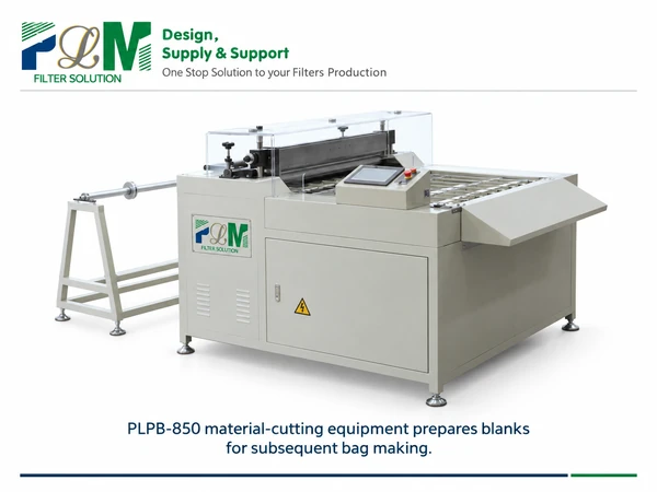
The PLPB-850 Auto Cutting Machine For Fabric Bag Filter is used for cutting fabric bag-filter material. Its electrical control allows cutting-length adjustment, and the product page describes a straight, neat cut edge that facilitates subsequent sewing. Cutting prepares the material; the bag-making operation must still suit the selected fabric and construction. During sample preparation, check whether the material feeds consistently and whether repeated blanks retain the required length and edge alignment. After joining, check the bag opening and finished length again. If the opening does not match the support parts, trace the cutting allowance and joining position before adjusting the downstream frame.
Clips and Inner Frames Must Match the Bag Opening
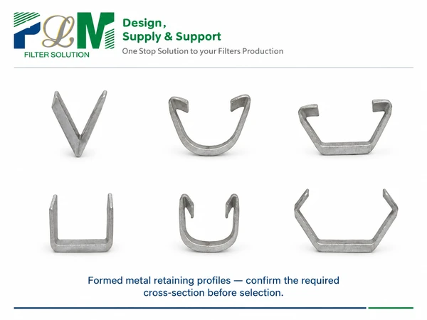
In the construction discussed here, metal clips and inner frames connect the flexible bag opening to the surrounding frame assembly. Their cross-sections, lengths and locating surfaces must correspond to the intended joint. Selecting a strip by length alone leaves its fit with the bag material and mating profile unresolved. The PLM-MFT-1 Automatic Clip Forming Machine serves clip-strip forming. For an L-shaped inner-frame route, the PLM-LNK-1318 L-Shaped Inner Frame Machine processes the corresponding metal inner frames. These machines prepare different components, so the required profile and drawing should determine their roles in the equipment plan.
A useful sample check brings the actual bag material, formed strip and inner-frame part together. Confirm that the opening can be positioned consistently and that the selected clamping or riveting arrangement secures the parts without visibly cutting, pulling or displacing the material. This checks the connection as an assembly, rather than accepting each part only by its separate dimensions. Visual and dimensional trial checks establish initial fit; they do not by themselves demonstrate connection strength or finished-filter performance. Define the verification methods and acceptance criteria in the product specification and retain the results. Check finished bag length, opening and joint position against the approved sample; check clip profiles and mating fit against the part drawing. Confirm connection retention and strength using the approved test method.
Outer Frame Forming Follows the Complete Assembly Dimensions
The outer frame receives the bag-and-support assembly and defines the finished filter’s external interface. Its internal opening must accommodate the assembled parts, while its external dimensions must meet the installation drawing. Check the frame section, corner closure and squareness together, because matching side lengths alone does not establish that the assembly will fit correctly.
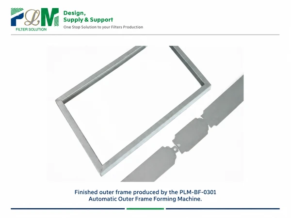
The PLM-BF-0301 Automatic Outer Frame Forming Machine is listed for forming bag-filter outer frames. Its specification states that a single machine produces a single profile width, with length adjustment within the model’s stated range. A manufacturer handling several profile widths should therefore confirm the configuration for those widths when planning equipment and changeovers. Keep the product outer frame distinct from any separate installation frame. PLM lists a Filter Mounting Frame Machine as a separate process option. Whether that operation belongs in the production plan depends on the supplied product and installation arrangement. A trial assembly should confirm that the bags, inner supports and outer frame meet the same drawing before batch production.
Assembly Output Depends on Component Supply and Joining Time
Once the parts fit, establish how they will be secured. The PLM-JTNK-1 Auto Strip Clamping Machine clamps frame bars to fix filter bags to frames. The PLM-MJNK-1 Automatic Inner Frame Riveting Machine is intended for riveting frame bars and securing bags. Clamping and riveting perform different joining actions; the product drawing should establish which action is required and where it occurs.
Compare equipment capacities on a common finished-filter basis. Material-cutting speed may be expressed in metres, forming capacity in pieces and clamping output in operations. Each completed filter consumes a defined quantity of bags and frame parts and requires a defined number of joining actions. Convert those requirements into the supply and assembly time needed for one finished filter, then include loading, positioning, inspection and changeover time. For each component, divide its usable output per hour by the quantity consumed per finished filter. For a joining operation, divide usable actions per hour by the actions required per filter. Use consistent units and count parallel machines explicitly. For a stable line with separate stations, the lowest converted capacity indicates the potential bottleneck; shared operators, sequential work and interruptions must also be included. Confirm sustainable output through a production trial rather than treating this calculation as a capacity guarantee.
This makes the configuration decision more practical. An existing workshop may need an additional forming or clamping machine at a constrained operation. A new line requires a coordinated plan for component preparation, work-in-progress storage, operator movement and assembly. Confirm the full process with representative materials and the intended size range, rather than selecting every machine from its individual speed rating.
Plan Bag Filter Equipment Around the Finished Product
For an initial equipment and process review, prepare:
- Bag material, finished bag length, bag count and approved sample bags.
- Frame dimensions, inner and outer profile sections, and product drawings.
- The intended size range, joining method and connection acceptance criteria.
- Target output, existing equipment, operator arrangement and current constraints.
Share these details and available drawings with us at [email protected]. We can discuss cutting, forming and assembly equipment, with the connection details and production sequence confirmed through samples and drawings